UPS, BESS, and Generators Are Not Interchangeable: The Three-Layer Power Architecture of an AI Data Center
Key Highlights
- Large digital loads, including data centers and crypto farms, can rapidly change demand, challenging existing grid stability and reliability standards.
- Current backup layers—UPS, generators, and site BESS—have limitations in handling instantaneous load swings and sustained disturbances caused by AI and crypto activities.
- Emerging solutions involve integrating medium-voltage PCS-based systems that combine UPS and BESS functions, providing both no-break transfer and load shaping capabilities.
- Regulatory bodies like FERC and ERCOT are implementing minimum ride-through and connection time requirements, shifting responsibility for grid stability from utilities to demand-side assets.
- The evolving power infrastructure emphasizes layered responses, with each layer addressing specific fault types and operational questions, moving towards more resilient and adaptive energy systems.
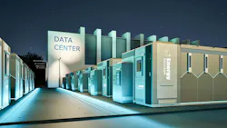
On July 16, the Federal Energy Regulatory Commission (FERC) gave independent grid system operators and other industry leaders a deadline: Reliability Standards covering computational loads — data centers and crypto mining — must be filed by Dec. 31, with registry criteria and a Phase II work plan due by March 1, 2027. FERC's framing of why: certain large loads "have the potential to change their demand almost instantly."
Two different problems drove that order, and they are usually discussed as one.
The first is that large digital loads have begun leaving the grid together. On 22 July 2026, after a transmission-line fault in Northern Virginia, roughly 3 GW of data-center load transferred itself to backup power — about 3% of PJM's demand. Reuters and the trade press, quoting PJM and Dominion Energy, described a voltage disturbance observed as far as Chicago and some ten minutes to stabilise a system that normally corrects one in milliseconds.
The documented case is older. On July 10, 2024, auto-reclosing after a 230 kV arrestor failure in the Eastern Interconnection produced six faults inside 82 seconds, every one cleared correctly. The North American Electric Reliability Council (NERC) incident review records "an approximate 1,500 MW of load reduction. None of this load was disconnected from the system by utility equipment; rather, the load was disconnected on the customer side by customer protection and controls" — "exclusively data center-type load," of which roughly 1,260 MW "did not return for hours." NERC attributes most of it to the interaction between that reclosing sequence and a facility scheme counting disturbances, typically three inside one minute, which transfers the site to backup and holds it there until a manual retransfer.
Nothing failed in either event; every protection scheme did what it was set to do. FERC's order puts the mechanism in numbers, citing a NERC finding on the extreme case — crypto-mining facilities, which "can lose between 17% and 95% of pre-disturbance consumption within milliseconds of a normally cleared transmission fault."
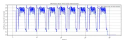
The second problem belongs to AI: the load itself moves, ramping and collapsing as jobs checkpoint and communicate. Microsoft, OpenAI and NVIDIA, in a joint 2025 paper on power stabilization, report that training traces concentrate their spectral energy between 0.2 and 3 Hz — a band the grid damps poorly and that no generator was ever designed for.
Both problems correspond to the same site structure, and let’s look into three layers in the order they were built to see which is responsible for what. Two layers are old.
The UPS owns the break
IEC 62040-3 (Edition 3.0, 2021) scopes itself to low-voltage AC systems with storage up to 1 500 V DC whose "primary function [is] to ensure continuity of load power." Continuity, not endurance.
Hence the sizing rule: a UPS is sized by transfer time, not outage duration. Its energy covers the sag, the transfer, and the start-and-load-acceptance of the generator behind it. Around 15 minutes, not hours and 0 transfer time to batteries.
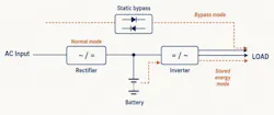
The load is always fed from the inverter and the grid only feeds the rectifier, so when anything upstream misbehaves, the correct reaction of the layer is to stop drawing on the grid and run from the battery. Which is the root of the reliability problem: nobody ever specified how the UPS should behave toward the grid. The threshold was set to protect the load, and from the site's point of view a transfer is a success rather than an event. Multiply it by the density of Northern Virginia and the same success becomes 3 GW of demand vanishing in seconds.
The generators own the fuel
The other historical layer is the generator, and its product is duration: where a UPS is designed for minutes, commonly around fifteen, the generator carries the site for as long as fuel keeps arriving.
Then there is the thing generators are bad at: being handed a large load at once. ISO 8528-5 contains no single step-load percentage of the kind vendor conversations imply. It gives guide values read off curves as a function of brake mean effective pressure, noting that a higher bmep "usually makes loading in several steps necessary." Load acceptance is tested as increasing steps; only load rejection is a single 100% event. In Kohler's reading of the 2022 edition, class G3 — what most industrial sets meet — allows 3 seconds for frequency to recover and 4 for voltage, and calls a 0-to-100% single step "an unrealistic scenario."
That ladder models load added in ascending stages: the start-up problem. It says nothing about a large swing arriving repeatedly at a set already running, which is the AI problem — and in my judgement, as engineering opinion rather than published finding, the more serious of the two. A set answers each step with governor and rotating inertia, so a duty that keeps stepping it works the fuel system, turbocharger and crankshaft in ways a staged-acceptance test never covers.
What the layer may be used for is decided by the rating plate and the air permit. Uptime Institute is explicit that for its top two tiers "only continuous ratings, derated prime ratings or standby ratings with no runtime limitations qualify" — a machine that can be run, not merely started.
The site BESS owns the shape
Put the two old layers side by side and the gap is obvious. The UPS leaves the grid the moment the grid misbehaves. The generators hold the site for days, but want their load in stages and do not enjoy being modulated. Neither can make the AI campus look like a well-behaved customer, because loads got this large and this fast.
Heritage explains the middle layer's limits. Grid-scale storage grew up as a bidirectional PCS on the medium-voltage side, connected in parallel with the utility and sized for trading and grid services. A parallel, grid-following converter cannot be a no-break source for anything downstream of it, there always will be some switching time, which is the gap the UPS was built to fill.
So the site battery sits on the medium-voltage side, rated in megawatts and megawatt-hours rather than minutes of critical load. Its product is not continuity; it is the shape of the load the grid sees. Four major duties: smoothing peaks so the connection can be smaller than the campus, cutting generator starts, absorbing the training swings neither neighbour handles well, and earning through grid services where the market allows.
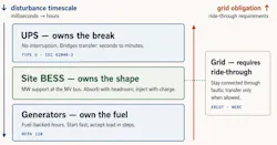
That last duty is becoming a condition of connection. Ireland's regulator decided in December 2025 that data centres with maximum import capacity of 10 MVA or more "are required to provide dispatchable onsite or proximate generation and/or storage capacity which matches their MIC" — with no ramp to full import capacity until it is delivered.
Why substitution fails in both directions
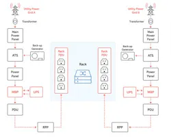
A site BESS is not a UPS. What decides which fault takes which load down is the redundancy topology — A and B distribution, dual-corded loads, static transfer switch, static bypass, 2N against N+1 — not the layer stack. A low-voltage feeder fault is cleared by the switchgear between it and the battery, and megawatt-hours on the MV side do nothing about it.
A UPS is not a site BESS. Sized for minutes of critical load, at the wrong connection point to shape what the grid sees. Its energy can be sold — bidding UPS batteries into fast frequency response is exactly that — but only above a reserved floor interlocked to the autonomy obligation.
Generators are neither. Ten seconds is a geological era to a GPU cluster and little slack for the machine: NFPA 110's Type 10 is the maximum permitted interruption at the transfer switch, and on a paralleled campus much of it goes to transfer delay, arbitration and synchronising rather than cranking.
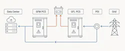
The boundary is moving, and the interesting equipment sits on it. Medium-voltage static UPS already exists. What is emerging is the obvious combination: a medium-voltage, PCS-based machine with the control authority for a no-break transfer and the energy to shape a campus — a UPS by function, a BESS by construction. Ask which of the two jobs it has been tested doing, and under which standard.
The interconnection queue has made this urgent. Where a grid connection is years away, an on-site plant can be standing in a fraction of that time, so AI campuses are increasingly energised behind the meter on their own gas turbines and reciprocating engines, with the utility connection following later — or not at all. Analysts now count tens of gigawatts of planned on-site gas generation before 2030, and the hyperscalers have been contracting turbine capacity since 2024. Some of it is not purpose-built plant at all: ex-aviation engines mounted on trailers are being pressed into service as bridge power.
Which quietly removes the shock absorber. On the grid, a campus's fluctuation is shared across every machine on the system and damped by all of them. Behind the meter there is no system to share it with, so the same swing that a large interconnection barely registers arrives in full at a handful of machines the operator owns — and it arrives as load-following duty on plant whose economics assume steady running. These oscillation is harder duty than baseload: it adds thermal and mechanical stress, shortens the interval between inspections and possible mechanical damages. The fatigue arithmetic above applies unchanged, except that the shaft life being spent now sits on the balance sheet of the company spending it.
This is the strongest commercial case for the middle layer. Put a BESS between the compute and the generation and the machines stop seeing the oscillation: the battery takes the swing while the turbines hold a near-constant load, with fewer starts, fewer deep excursions, and maintenance intervals that reflect running hours rather than abuse. The trade is that the battery becomes reliability-critical rather than optional.
The grid stopped treating this as the customer's business
NERC's review of the 2024 event asked transmission operators and planners for dynamic response models of large loads, studies of how much load a fault could remove, and load ramp rates in operating agreements. A Level 2 Alert followed in September 2025; of the 55 entities reporting established criteria, "many indicated that there is no voltage ride-through, recovery, or other voltage response data submission requirements to evaluate this performance." In May 2026 a Level 3 Essential Action asked planners to "ensure no non-consequential loss of firm load for computational load from normally cleared non-bus faults." None of it was mandatory — which is what FERC's order set out to change.
ERCOT got there first: approved July 9, 2026 and effective that August, its Nodal Operating Guide section for Large Computational Loads sets minimum connected times at the service delivery point.
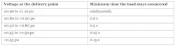
Read those as no-trip minima to be set with margin, and note the carve-out: below 0.35 pu, cooling and mechanical load may ride through or trip regardless of duration. Texas only, and loads energised before November 2025 are largely exempt.
The category is what changed. Low-voltage ride-through used to be demanded of generators and inverter-based resources; it is now demanded of demand — and the settings that deliver it sit inside equipment the utility does not own, specify or inspect. So the disturbance-counting logic is now a grid-interconnection parameter. Find where yours lives — UPS controller, transfer-scheme relay, or power-monitoring system — and review it alongside the ride-through study.
Dividing the duty
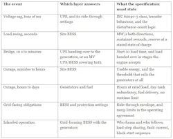
These are not competing technologies. They answer different questions — was there a break? What shape did the grid see? And how long can this run without a tanker? — and the failure mode of the whole architecture is a layer being asked somebody else's question.
About the Author
Sergey Syrvachev
Sergey Syrvachev is director, Product Engineering at HyperStrong International USA Corp.